I quite agree Ciaran! Its the small jobs that usually get left because of other more serious things to attend to.
Here is what I did.... Its an idiots guide...really it is too detailed!
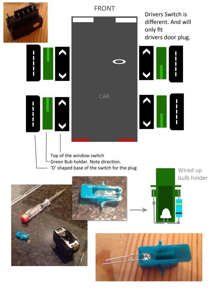
1) Get switch out of the door. Easy Peasey!!...I would do one at a time. You'll no doubt know this, the drivers door has its own plug, so only that switch will fit it..... The other three are interchangeable.
2) Take the arrowed button pad off the switch... even more easy Peasey! Make note of the green bulb holder and its direction. I put a little sticker on the switch to remind me. There is no obvious markings to go by.
3) Prise the green holder out with pliers or a small screwdriver. Then you'll see the bulb and the hair like wires. Take bulb out. Extremely easy!
4) I then used a small screwdriver to enlarge the two little groves for the wires. The LED wires are far thicker and to seat the LED, they need to be slightly bigger. I got my LEDs of Ebay, they are 3mm bright white 12v with correct 12V resistors.
5)Take an LED...Long leg is + short leg is - , and put in so that the bulb is as close to the edge of the holder as poss. So both legs are sticking out as much as possible. You can then bend the bulb up, so it points up into the holder to give better light output. All explained on the attachment.
6) I then took a resistor and using the Dutch guide, tucked it in as much as poss on the positive leg side. you can wrap the wire around the little peg. Then bend round the positive leg on the LED 90 degrees, so it meets with the resistor leg. tricky bit...solder them together. You'll have loads of off cut. I bent the resistor wire around the LED leg and soldered. Try not to get big blobs of solder on the joins. Its tight in the switch and as you might find, large blobs will foul the inside mechanism. It is fiddly...I used large blocks of blue tack to hold everything whilst soldering!

7) You can then bend the - neg arm around the holder. You'll note it is too short and wont meet the peg it has to wrap around. I used the softer thinner resistor wire I cut off from the positive arm and soldered that on to extend the wire and then wrap around the peg.
8) Now you can take it all off and test using a normal 9V battery to see if it all lights up. LEDs rely on correct polarity to work. So pos to pos and neg to neg. Obvious stuff.
If it does light up okay, rebuild the switch,....it will be a tight fit. you might need to cut of some excess wire around the pegs, but it should fit back snuggly. Make sure the button legs don't rub against the resistor or the wires. I bent them back closer to the green holder with a small screw driver whilst in situ.
9) Now take off the button pad and refit the switch in the car without it. Turn ignition on and it should light up. If it doesn't, DO NOT TOUCH ANY OF THE SWITCHES. YOU"LL BLOW A FUSE IF YOU TRY TO OPEN THE WINDOWS!!.....just switch off ignition and take out the green holder, turn the green holder around so it points the other way, refit and switch ignition on. You should then be bathed in a bright green light! My diagram should help you here.
The seat switches inside are exactly the same. They just have a different top to them so same principal.